flip flop flip flop - Circuitos electrónicos

 Prob_7
 Problemas propuestos · El circuito de la figura corresponde a un sumador serial que ha sido estudiado como un flip-flop en el tema VI. Analizar el [. ]
http://personales.unican.es/manzanom/Planantiguo/EDigitalI/Prob_7.pdf
Comencemos. . . Los circuitos biestables son muy conocidos y empleados como elementos de memoria, ya que son capaces de almacenar un bit de información. En general, son conocidos como Flip-Flop y poseen dos estados estables, uno a nivel alto (1 lógico) y otro a nivel bajo (cero lógico). . .
http://r-luis.xbot.es/edigital/ed12.html
Generalidades. Flip-Flop. Contadores de pulsos. Divisores de frecuencia. Multiplicadores de frecuencia. Comparadores digitales. Registros de desplazamientos. Multiplexor y de-multiplexor.
https://www.monografias.com/trabajos14/flipflop/flipflop.shtml
This is an extension of the CMOS toggle flip flop circuit with the addition of two bandpass filters and condenser microphone so the relay can be toggled by whistling at it. The condender mic used is a PC board mount Radio Shack #270-090C.
http://www.circuit-finder.com/categories/sensor/sound-sensor/577/whistle-on-whistle-off
En esta publicación os presento un interesante proyecto muy fácil de hacer y práctico, que nos permitira comprobar continuidad en pistas de circuitos y cables, por decir alguna de las utilidades que le podeis dar al instrumento. Esquema eléctrico (pinchar para ampliar)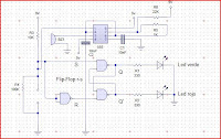 Lista de componentesRes.......
https://roboticayelectronica.blogspot.com/2010/11/tester-de-continuidad.html
Digital frequency dividers usually use flip-flop stages that connect the Q pin to the D data-input pin of the following stage. This configuration...
http://www.edn.com/design/test-and-measurement/4347165/Circuit-divides-frequency-by-N-1
Flip-Flop Tipo T con Flip-Flop JK - Flip-Flop Tipo D con Flip-Flop JK. Conectar un FF JK para obtener un FF D y FF T. Diferentes tipos de entradas de reloj
https://unicrom.com/dig_FF_JK.asp
MC10H131-D.PDF ? Semiconductor Components Industries, LLC, 2016 August, 2016 Rev. 81Publication Order Number: MC10H131/D MC10H131 Dual D Type Master?Slave Flip?Flop Description The MC10H131 is a MECL 10H? part which is a functional/pinout duplication of the standard MECL 10K? family part, with 100% improvement in clock speed and propagation delay and no increase in power-supply current. Features.......
http://www.onsemi.com/pub/Collateral/MC10H131-D.PDF
 Primero que nada una breve introduccion a lo que es el 555, para entender su funcionamiento usaremos la tabla de verdad del flip flop 555(ver imagen), si el voltaje en el pin 6 es mayor a 2/3 de vcc S esta en 1 logico, y si el voltaje en el pin 2 es menor que 1/3 vcc R esta en uno logico, cuando Qm+1 esta en vcc o en uno logico se activa el trans.......
https://bottomviews.blogspot.com/2007/08/circuito-monoestable.html
transistor tester using dual j k flip flop circuit diagrams. Search DIY electronic projects and circuit diagrams with descriptions. Learn electronics.
http://www.high-voltage-lab.com/search/transistor-tester-using-dual-j-k-flip-flop
 I have a new piece up in the Fox Forum:"Obama Blinks on Prison Photos: Courage or Subterfuge?""The way I see it, there are three likely circumstances that could explain this 147th flip-flop on the interrogation issue and whether or not prosecuting the Bush administration is something Obama wants to do. (It would seem an easy enou.......
https://red-secupp.blogspot.com/2009/05/courage-or-subterfuge.html
In this project, we will show how to build a D flip flop with NAND gates.
http://www.learningaboutelectronics.com/Articles/D-flip-flop-circuit-with-NAND-gates.php
Inicialmente para este tipo de problemas uno piensa en un comparador de ventana con dos amplificadores operacionales. El problema es que este tipo de circuitos reacciona solo ante una señal electrica de entrada solo para saber si una señal o nivel de tensión está dentro o fuera de un límite aceptable. Con ayuda de un comparador (amplificador operacional) que controle el nivel superior y otro comparador que controle el nivel inferior, se puede implementar un comparador de ventana. Sin embarg.......
https://jorgefloresvergaray.blogspot.com/2010/04/detector-automatico-de-nivel-de-agua.html
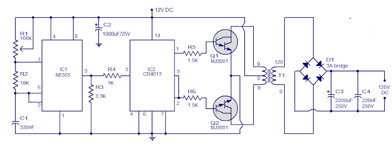 Its a simple circuit of 12V DC to 120V DC converter. The circuit consists of two phases first phase of the investor base and then a rectifier and filter stage. IC1 NE555 is wired as an astable multivibrator operating .......
https://audio-schematic.blogspot.com/2011/08/simple-circuit-12v-to-120v-dc-dc.html
The circuit of 500 Watt Inverter 12VDC to 220VAC is made using a transistor. central component of this inverter circuit is a configuration of 2 pieces of transistors Q1 and Q2 which form a circuit of Flip-Flop. The output of the flip-flop Q1 and Q2 then in severance for each pulse to complement each other using a compiled circuit by Q3 and Q4. Output which complement each other is then given to the driver transistors Q5 and Q6 form the transistor 2SC1061. Power Inverters of this circuit is compo.......
https://elektroarea.blogspot.com/2011/06/500-watt-inverter-12vdc-to-220vac.html
1 2 3