speed control - Circuitos electrónicos

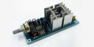
This circuit can be used to control the speed of a motor by adjusting the duty cycle of the pulses sent to the motor.
Circuitos electrónicos
http://www.electronica-electronics.com/en/Circuits/PWM-555.html
 Interfaz USB genérica para comunicación con dispositivos electrónicos (pdf).
 Interfaz USB genérica para comunicación con dispositivos electrónicos Avance de Proyecto Andrés Aguirre Carlos Grossy Rafael Fernández ¿Que es el proyecto? Una respuesta a la necesidad de comunicar de forma sencilla y genérica dispositivos [. . ]
Circuitos electrónicos
http://www.fing.edu.uy/inco/grupos/mina/pGrado/pgusb/Docs/Presentacion_Avance.pdf
Circuitos electrónicos
http://www.zen22142.zen.co.uk/Circuits/Interface/cmscontrol2.htm
Circuitos electrónicos
https://circuitos-de-electronica.blogspot.com/2007/10/electronic-roulette-game.html
Digital fan speed control circuit design for fans based induction motor. The speed can be varied wide range since it can alter the voltage input of the fan
http://circuitdiagram.net/digital-fan-speed-control.html
dc speed pwn control circuit diagrams. Search DIY electronic projects and circuit diagrams with descriptions. Learn electronics.
http://www.high-voltage-lab.com/search/dc-speed-pwn-control
As Moore's Law plunges us into the realm of multigigahertz processors and PCs with gigabytes of RAM, engineers face the task of removing the heat...
http://www.edn.com/design/analog/4333070/Circuit-provides-efficient-fan-speed-control
This circuit of a simple speed controller for a mini DC motor, uses PWM and can be used in tape recorders and toys. Full circuit diagram available here.
http://electronicsforu.com/electronics-projects/hardware-diy/speed-control-dc-motor-using-pulse-width-modulation
A continuously alive wiper in a car may prove to be a nuisance, abnormally back it is not aqueous heavily. By application the ambit declared actuality one can alter across-the-board amount of the wiper from already a additional to already in ten seconds. The ambit comprises two timer NE555 ICs, one CD4017 decade counter, one TIP32 disciplinarian transistor, a 2N3055 ability transistor (or TIP3055) and a few added detached components. Timer IC1 is configured as a mono- abiding multivibrator which.......
https://elektroniki.blogspot.com/2010/08/wiper-speed-control-circuits.html
IntroductionPIC12F683 has a built-in PWM module. The PWM output (CCP1 pin) is multiplexed with GPIO. 2 (pin 5). So the TRISIO<2> bit must be cleared to make the CCP1 pin an output. The objective of this experiment is to control the speed of a DC motor with an input from a potentiometer. This will be achieved in two steps:Read analog value (potentiometer output) through AN0 channel and generate a PWM wave at CCP1 pin (5) with duty cycle proportional to the analog value. Feed the PWM to motor driv.......
https://picboard.blogspot.com/2010/07/experiment-no-5-dc-motor-speed-control.html
https://bywiring.blogspot.com/2013/05/pwm-motor-speed-control-circuit.html
https://circuitelec.blogspot.com/2009/07/dc-motor-speed-control-circuit.html
https://scdiagramwiring.blogspot.com/2013/04/ceiling-fan-regulator-motor-speed.html
http://feedproxy.google.com/~r/ElectronicCircuit/~3/Z8ooOVuc_eU/dc-motor-speed-control-circuit.html
1 2 3