control de motor"; - Circuitos electrónicos

Esquema eléctrico control arranque y paro de un motor
https://esquemasyelectricidad.blogspot.com/2016/08/esquema-electrico-control-arranque-y.html
La aplicación de motores paso a paso (PaP) para cualquier implementación básica requiere de:Una señal de clock NE555 para el control de velocidad (rpm). Una señal para el Sentido de Giro (ClockWise/CounterClockWise). Una señal para determinar Paso Completo o Medio Paso en el motor (Full/Half Step). Un circuito de Control L297 que envía las señales a las bobinas a través del circuito de potencia. Un potenciómetro en Vref para controlar la máxima corriente de carga en el circuito choppe.......
https://apuntesdeelectronicaycontrol.blogspot.com/2014/07/driver-motor-paso-paso-unipolar-y.html
I've had a number of stepper motors sitting in my shop for years. If we really want to do anything fun with our Arduino, we are eventually going to have to run a stepper motor. So, here we go!A little background on stepper motors and how they are different compared to a typical electric motor. Unlike a conventional electric motor that spins when power is applied, stepper motors incrementally spin (step), allowing control over exactly how far the motor's shaft spins, even to the degree. Stepper m.......
https://pscmpf.blogspot.com/2010/07/arduino-stepper-motor-control.html
 Este segundo intento ha sido satisfactorio. En la primera ocasión se me bajaba el magnetotérmico de la vivienda y se me fundió dos optoacopladores de la placa del módulo de 8 relés. Básicamente lo que he hecho es esto indicado en el boceto de abajo.
 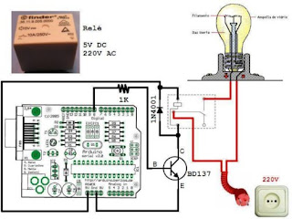 Para evitar fluctuacion.......
https://electronica-pic.blogspot.com/2016/01/control-reles-con-una-bombilla_5.html
IntroductionPIC12F683 has a built-in PWM module. The PWM output (CCP1 pin) is multiplexed with GPIO. 2 (pin 5). So the TRISIO<2> bit must be cleared to make the CCP1 pin an output. The objective of this experiment is to control the speed of a DC motor with an input from a potentiometer. This will be achieved in two steps:Read analog value (potentiometer output) through AN0 channel and generate a PWM wave at CCP1 pin (5) with duty cycle proportional to the analog value. Feed the PWM to motor driv.......
https://picboard.blogspot.com/2010/07/experiment-no-5-dc-motor-speed-control.html
AN2520 - Sensorless Field Oriented Control (FOC) for a Permanent Magnet Synchronous Motor (PMSM) Using a PLL Estimator and Equation-based Flux Weakening (FW) Application Note AN2520 - Sensorless Field Oriented Control (FOC) for a Permanent Magnet Synchronous Motor (PMSM) Using a PLL Estimator and Equation-based Flux Weakening (FW) Application Note........
http://www.microchip.com//wwwAppNotes/AppNotes.aspx?appnote=en599773
https://setppingmotor.blogspot.com/2013/05/bipolar-stepper-motor-control-circuit.html
http://www.nxp.com/applications/solutions-for-the-iot-and-adas/smart-connected-solutions-for-the-iot/smart-cities-in-the-age-of-iot/smart-mobility/77-ghz-radar-system/real-time-control-embedded-software-motor-control-and-power-conversion-libraries:RTCESL

https://www.elprocus.com/h-bridge-motor-control-circuit-using-l293d-ic
 dc-motor-control-circuit_orig.gif
 http://www.hobby-circuits.com/files/82/dc-motor-control-circuit_orig.gif
https://bywiring.blogspot.com/2013/05/pwm-motor-speed-control-circuit.html
https://cidigg.blogspot.com/2013/07/12-v-bidirectional-motor-control-circuit.html
1 2 3