2n2222 - Circuitos electrónicos

 Timbre electrónico con CD4017
 El oscilador de relajación tiene una frecuencia que depende de los valores de C2 y R14 más el valor del potenciómetro correspondiente conectado a cada una de las salidas del CD4017 El timbre electrónico genera nueve notas, totalmente manipulables con los 9 potenciómetros que varian la frecuencia a la que oscila el UJT. El multivibrador astable enviará su señal de salida a la entrada de reloj del contador de décadas (patita 14). La entrada del reloj de CD4017 estará habilitada siempre y .......
Circuitos electrónicos
https://elrincondeloscircuitos.blogspot.com/2011/01/timbre-electronico-con-cd4017.html
Esquema de un pequeño transmisor de frecuencia modulada FM de 3 voltios, diseño hecho con kicad schem.
Circuitos electrónicos
http://www.electronica-electronics.com/Transmisores/Transmisor_FM-R2/Transmisor_FM-R2-schem.html
El 2N2222, también identificado como PN2222, es un transistor bipolar NPN de baja potencia de uso general. ![]() Principales características Voltaje colector emisor en corte 60V (Vceo) Corriente de colector constante 800mA (Ic) Potencia total disipada 500mW(Pd) Ganancia o hfe 35 mínima Frecuencia de trabajo 250 Mhz (Ft) Encapsulado de metal TO-18 Estructura NPN Sirve tanto para aplicac.......
Principales características Voltaje colector emisor en corte 60V (Vceo) Corriente de colector constante 800mA (Ic) Potencia total disipada 500mW(Pd) Ganancia o hfe 35 mínima Frecuencia de trabajo 250 Mhz (Ft) Encapsulado de metal TO-18 Estructura NPN Sirve tanto para aplicac.......
https://elblogdelprofesordetecnologia.blogspot.com/2016/01/transistor-2n2222.html
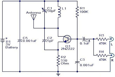 The FM transmitter circuit is using NPN transistor 2N2222. The L1 and C1 producess necessary oscillations Q1. The collector capacity C4, R3 and R4 resistor performs the function of the output mix theaudio to stereo player or i-emitter resistor R2 Pod........
https://audio-schematic.blogspot.com/2011/09/fm-transmitter-circuit-using-2n2222.html
Este micrófono tiene una muy buena estabilidad de frecuencia, aproximadamente 1Km de alcance (en condiciones ideales) y tiene excelente sensibilidad de audio. Todo esto se logró agregando un amplificador de RF (con 10dB de ganancia) y un pre de AF que refuerza la modulación a su punto ideal.  Es muy fácil de construir. L1 está formada por 3. 25 vueltas en espiral, que forman parte del dibujo.......
https://elrincondeloscircuitos.blogspot.com/2011/03/microfono-inalambrico-por-fm.html
Camp ended on Friday -- 21 campers went home happy with a fully-functional Arduino-powered robot. I'll post some photos and thoughts on the camp in another post, but today. . . back to Make: More Electronics!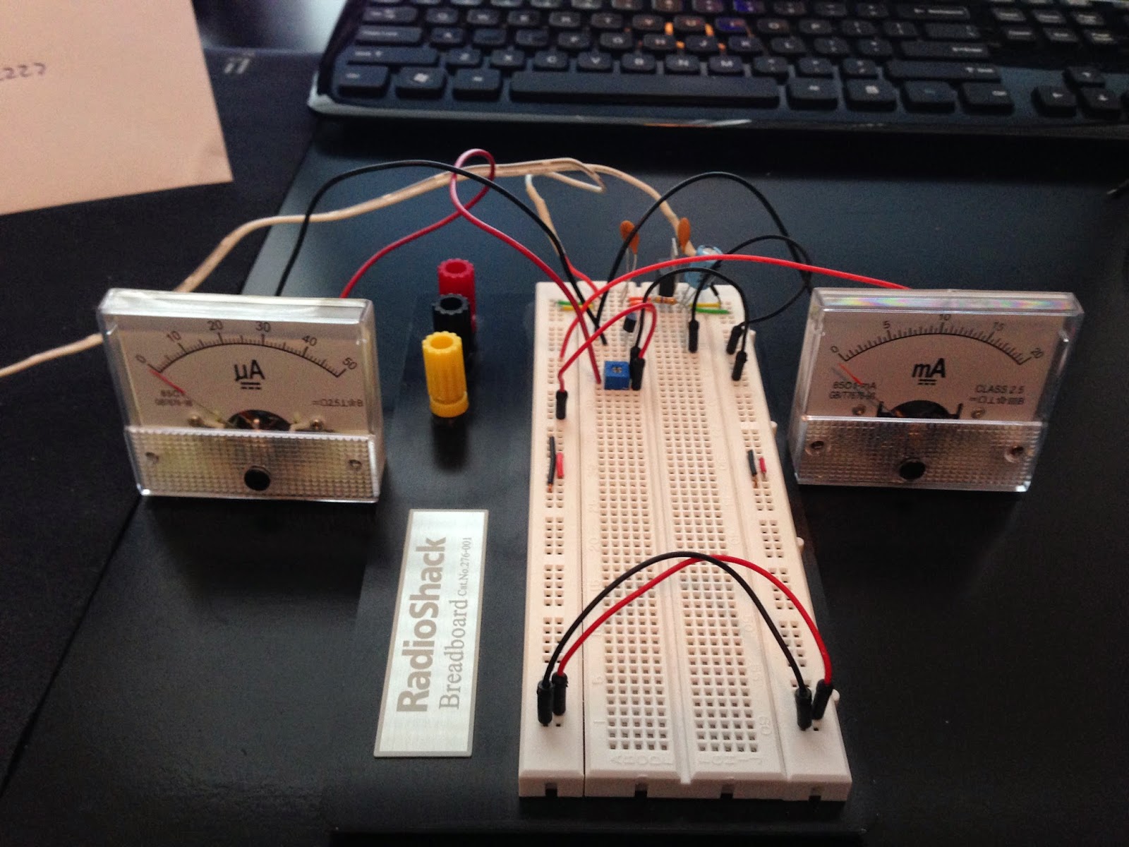 Back in Chapter 2, Charles shows how he connected up two analog gauges to record milliamps and microamps, and that's exactly what I've done. Look carefully on the back of t.......
https://handsonmoreelectronics.blogspot.com/2014/06/experiment-2-revisited.html
 EL TIMER 555Este excepcional Circuito Integrado muy difundido en nuestros días nació hace 30 años y continúa utilizándose actualmente, veamos una muy breve reseña histórica de este C. I. . Jack Kilby ingeniero de Texas Instrument en el año de 1950 se las ingenió para darle vida al primer circuito integrado, una compuerta lógica, desde.......
https://miguelangelrequiz.blogspot.com/2009/07/timer-555.html
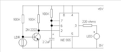
 El circuito integrado a usar es el muy difundido timer 555 y un transistor de uso general tam.......
https://ramon-electronica.blogspot.com/2011/01/detector-de-oscuridad.html
Here's 75 Meter QRP SSB Transceiver. In general, the transceiver switches the 4-element 1500 ohm xtal BPF ends between the inputs and outputs of the two SA602s to reverse the signal flow for R/T operation. Since no IF amplifier is used in the design, 20 dB of additional receiver gain is produced by the 2N2222 receiver RF amplifier, while automatic gain control (AGC) is produced by the peak DC swing of the LM386 output passed through a rectifier and filtered by a capacitor and fed to the gate of .......
http://www.electronics-diy.com/75-meter-ssb-transceiver.php
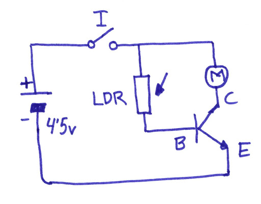
Propuesta de trabajODiseñar y construir un cochecillo que sea controlado por la luz de una linterna. El coche se pone en funcionamiento cuando la luz incide sobre la célula, parándose a medida que se va oscureciendo. Solución adoptadaCircuitor eléctrico. Los operadores electrónicos que vamos a utilizar en este proyecto son el transistor y la célula fotoeléctrica. (Concretamente hemos utilizado la célula LDR y el transistor 2N2222). El circuito electrónico será el siguiente:
https://elblogdelprofesordetecnologia.blogspot.com/2016/02/cochecillo-con-celula-fotoelectrica-y.html
So, this is a little project I did almost in the middle of my exam period, which finished a week ago. It is basically a substitution of a thermostat, regulating heating appliances in an apartment. It is web controlled and monitored, and works in auto and manual mode. 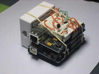 It consists of an Arduino (Duemilanove), an Arduino Ethernet Shield, a temperature s.......
https://diyistheway.blogspot.com/2009/03/thermosmart.html
The circuit as shown act as a light detector. Under normal conditions the resistance of the LDR is high, keeping pin 2 low. When light falls onto the LDR the resistance drops to a couple hundred ohms and triggers pin 2 high which biases the base of Q1 via pin 6 and R4 and in turn activates the relay.  Light/Dark switch Circuit with relayAs y.......
https://elektroarea.blogspot.com/2011/05/lightdark-switch-with-relay.html
Univox Super-Fuzz 47k 22k 220k 10k 22k 470 10k 100k 1k8 100k 0. 1uf 100k 47k 470k 10k 270k 50k Drive 10k 22k 1k8 100k 470 100uf/10v + 0. 001uf Notch Level 100k 10k 47k 10k 10k 22k Normal 0. 1uf 50k 100k 15k 1k IN = high gain NPN; 2N2222, [. . . . . ].......
http://circuitdiagram.net/download/univox-super-fuzz-circuit-design?wpdmdl=3531
 Sencillo Receptor De AM
 Comunidad de discusion sobre Automatización, Electrónica industrial y de potencia, Microcontroladores y electrónica digital, Robótica, Domótica, Telemática, Tecnologías móviles, Sistemas de Audio, Sistemas de Video, y muchos temas más.
https://www.forosdeelectronica.com/proyectos/receptor-AM.htm
 OSCILADORES_COLPITTS
 OSCILADORES COLPITTS A CRISTAL DE 4 MHz RESUMEN En el siguiente laboratorio se presenta un informe con relación a un circuito oscilador a cristal y [. ]
http://natamonitoreo.tripod.com/OSCILADORES_COLPITTS.pdf
1 2 3