PWM - Búsqueda para electrónicos
Simple pulse width modulation - PWM DC motor controller using a MOSFET. This kind of connection is to prevent heat and minimize the power consumption
http://circuitdiagram.net/pwm-dc-motor-controller-mosfet.html
PWM con un 555. Control de velocidad de motores de continua con un CI 555. Completo con esquema, circuito impreso y simulación
http://www.electronica-electronics.com/Circuitos/Variador_de_velocidad.html
Using a CMOS version of the 555 timer, this circuit can be used to control the speed of a motor by adjusting the duty cycle of the pulses sent to the motor
http://www.discovercircuits.com/H-Corner/555 timer-simple pwm2.htm
pwm 30 amp heavy duty 3khz dc circuit diagrams. Search DIY electronic projects and circuit diagrams with descriptions. Learn electronics.
http://www.high-voltage-lab.com/search/pwm-30-amp-heavy-duty-3khz-dc
This inverter uses PWM (Pulse Width Modulator) with type IC SG3524. IC serves as a oscillator 50Hz, . . . [[ This is a content summary only. Visit my website for full links, other content, and more! ]]
http://feedproxy.google.com/~r/Electroniccircuitandschematic/~3/VEV-iLRG1FY/inverter-5000-watt-pwm.html
Download a datasheet or document on TIs TL494 Offline and Isolated DC/DC Controllers and Converters, from the PWM and Resonant Controller collection of analog and digital product folders. # Added
http://www.ti.com/product/TL494
http://homepages.which.net/~paul.hills/Circuits/PwmGenerators/PwmGenerators.html
Página dedicada a la Radioaficion
http://lu8eha.com
PWM IC is enhanced with discrete components for wider-range operation.
http://www.edn.com/design/analog/4325204/Buffer-amplifier-and-LED-improve-PWM-power-controller-s-low-load-operation
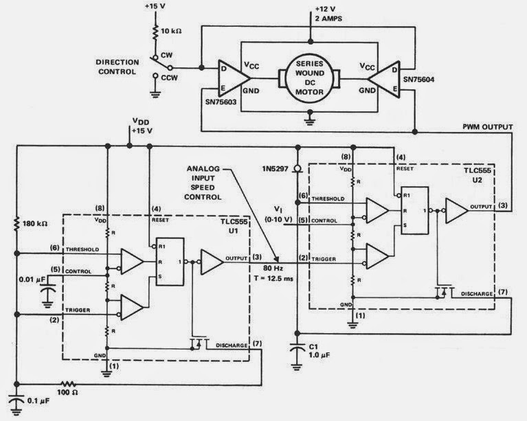 Here the circuit diagram of PWM Controller which uses complementary half-H peripheral drivers SN75603 and SN75604, with totem-pole outputs rated at 40 V and 2. 0 A. These drivers effectively place the motor in a full-bridge configuration, which has the ability to provide bidirectional control. Timer U1 operates in the astable mode at a frequenc.......
https://skema-elektronik.blogspot.com/2014/06/pwm-controller-circuit-using-sn75603.html

The post discusses a 5kva PWM sinewave inverter circuit using compact ferrite core transformer. The idea was requested by Mr. Javeed.The Requestdear sir, would you please modify its output with PWM source and facilitate to make use such an inexpensive and economical design to World wide needy people like us? Hope You will consider my request. Thanking you. Your affectionate reader. Javeed AhmedThe Design In one of my previous post I introduced a ferrite core based 5kva inverter circuit, but sinc.......
http://www.homemade-circuits.com/2016/02/pwm-sinewave-5kva-inverter-circuit.html
https://asuvro.blogspot.com/2012/11/triangular-sawtooth-and-square-wave.html
https://basicelectronic.blogspot.com/2009/01/pwm-generator-with-current-limit.html
https://bywiring.blogspot.com/2013/05/pwm-motor-speed-control-circuit.html
 Documentos sobre PWM en PDF
Buscar artículos relacionados en AMAZON