555 556 - Búsqueda para electrónicos
 lm556
lm556 LM556 LM556 Dual Timer Literature Number: SNAS549 LM556 Dual Timer March 2000 LM556 Dual Timer General Description The LM556 Dual timing circuit is a highly stable controller capable of producing accurate time delays or oscillation. The 556 is a dual 555. Timing [. ]
https://www.learnabout-electronics.org/Downloads/lm556.pdf
 EL TIMER 555Este excepcional Circuito Integrado muy difundido en nuestros días nació hace 30 años y continúa utilizándose actualmente, veamos una muy breve reseña histórica de este C. I. . Jack Kilby ingeniero de Texas Instrument en el año de 1950 se las ingenió para darle vida al primer circuito integrado, una compuerta lógica, desde.......
https://miguelangelrequiz.blogspot.com/2009/07/timer-555.html
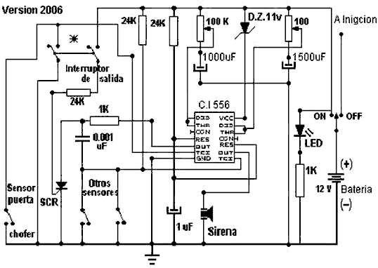
Alarma para auto con 556. Circuito alarma para automóvil con el circuito integrado (C.I.) 556 que tiene dos temporizadores 555
https://unicrom.com/alarma-para-auto-con-556
I really liked this project. Combining two 555 timer chips really helped cement how this little chip works. I had forgotten much about the pins and how the 555 functioned, so wiring up this circuit was very helpful. I highly recommend that as you wire up each 555 timer chip, you examine carefully the wires that connect to each pin and try to understand exactly what is happening at each pin.  You'll probably find as I .......
https://handsonmoreelectronics.blogspot.com/2014/07/experiment-5-chapter-5-red-alert.html

In this article we learn how to make a multilevel (5 level) cascaded inverter circuit using a very simple concept developed by me. Let's learn more regarding the details. In this website so far I have developed, designed and introduced many sine wave inverter circuits using straightforward concepts and ordinary components such as IC 555, which happen to be more result oriented instead of being complex and full of theoretical jumbles. I have explained how simply a high power audio amplifier can b.......
http://www.homemade-circuits.com/2015/12/simple-5-level-cascaded-sine-wave.html
1N4001 LM556 LM556 Dual Timer Literature Number: SNAS549 LM556 Dual Timer March 2000 LM556 Dual Timer General Description The LM556 Dual timing circuit is a highly stable controller capable of producing accurate time delays or oscillation. The 556 is a dual 555. Timing [. ]
https://www.learnabout-electronics.org/Downloads/1N4001.pdf
all about ALARM PROJECTS and CIRCUITS, compilation of electronic projects for dummies and students, downloads of electronic softwares, ebooks, datasheets, and tutorials in electrical electronic and related engineering topics
https://electronic-dummies.blogspot.com/2009/10/alarm-circuits.html
repeater-fan-controller-1 A Simple Repeater Fan Controller By Robert E. Shepard - KA9FLX Unlike many repeater systems, our local club repeater has always been located within a member's home, many times in a basement or in this case, my home office area. The latter created a desire to lower the noise level generated by the repeater, specifically,.......
http://www.repeater-builder.com/projects/pdfs/repeater-fan-controller-1.pdf
The circuit illustrates generating a single positive pulse which is delayed relative to the trigger input time.
http://www.circuit-finder.com/categories/timer/638/generating-a-delayed-pulse-using-the-555-timer
Alarma para auto con 556. Circuito alarma para automóvil con el circuito integrado (C.I.) 556 que tiene dos temporizadores 555
https://unicrom.com/?p=1736
alarma para auto con temporizadores 556
https://www.electronicafacil.net/circuitos/esquema196.html
https://555timer-elektro.blogspot.com/2013/05/us-police-siren-circuit-using-555-timer.html
Documentos sobre 555-556 en PDFBuscar artículos relacionados en AMAZON