transformer - Circuitos electrónicos

flyback transformer bsc27 z4206 circuit diagrams. Search DIY electronic projects and circuit diagrams with descriptions. Learn electronics.
http://www.high-voltage-lab.com/search/flyback-transformer-bsc27-z4206
 iw1790_product_summary
 iW1790 Highly Integrated AC/DC Primary-Side Rapid ChargeTM PWM Controller Supporting XM-Comm Technology 1 Description The iW1790 is a high performance AC/DC power supply controller for rapid charge that uses main transformer communication (XM-Comm) technology to minimize external component count and simplify system design. The device operates in quasi-resonant mode to provide high efficiency and it also provides [..].......
https://www.dialog-semiconductor.com/sites/default/files/iw1790_product_summary.pdf
This low-cost, switchable, dual-impedance transformation circuit comprises a single conventional transformer and two minimum-loss pads.
http://www.edn.com/design/test-and-measurement/4317916/Audio-test-accessory-isolates-and-matches-loads
A1. Transformer, rectifier, filter, regulator. A2. To change ac to pulsating dc. A3. To change pulsating dc to pure dc. A4. To maintain a constant voltage to the load.A5. The half-wave rectifier. A6. 15. 9 volts. A7. It isolates the chassis from the power line. A8. The fact that the full-wave rectifier uses the full output, both half cycles, of the transformer........
http://www.tpub.com/neets/book7/27p.htm
Joseph Diverdi Input voltage from high voltage DC DC converter is 12V AC at 800mA current and then converted to DC through a bridge rectifier Diode 1A. The voltage output of converter circuit can be adjusted in the range of 0-1000V DC. This high voltage DC DC converter uses the transformer
http://www.radiolocman.com/shem/schematics.html?di=71052
22404-21700di O ccasionally,you haveaccess to a transformer for powering a dc circuit,but its output volt- age is much higher than that required for the dc voltage. The full-wave-rectified and filtered output ofan ac input voltage V X , is V DC 41.414V X 22V F ,where V F is the forward drop in the rectifier (ap-
https://m.eet.com/media/1149121/22404-21700di.pdf
electronics_project_01_15 ELECTRONICS PROJECTS Vol. 19 178 AUTOMATIC EMERGENCY TORCH J ust don't think that this is yet another addition to other emer- gency light circuits published in EFY earlier. This circuit is a hit different. Its main features are: 1. Very reliable operation. 2. As transformer is not used, it is compact and cost-effective.3. The torch bulb.......
http://bhagyaparmar.weebly.com/uploads/5/2/7/8/5278806/electronics_project_01_15.pdf
EJ67 Volume Sixty-Seven LETTER FROM THE CEO IN-DEPTH ARTICLES Reduce System Cost for Advanced Powerline Monitoring by Leveraging High-Performance, Simultaneous-Sampling ADCs Overcome the Challenges of Integrating HB LEDs in Automotive Systems Minimize Voltage Offsets in Precision Amplifiers Improve Two-Phase Buck Converter Performance with a Coupled-Choke Topology 2 3 8 14 17 PHASE 1 VOLTAGE TRANSFORMER AIN0 CURRENT TRANSFORMER AIN1 AVDD ADC ADC VN NEUTRAL IN AIN2+ [..].......
http://pdfserv.maximintegrated.com/en/ej/EJ67.pdf
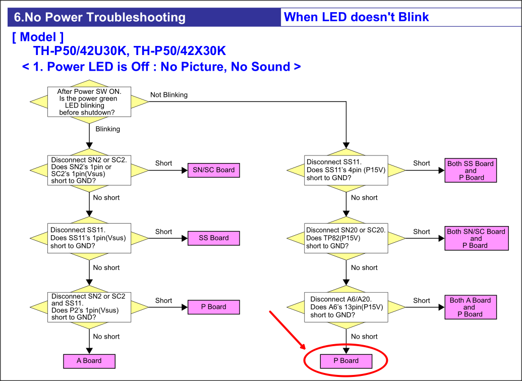
This is my own Plasma TV. Symptom, sudden power cut off. Power LED not lit at all when the side power button switched on. According to the service manual [ th_p42x30d_g_k_m_p_s_v_1. pdf ] , this is power board issue. 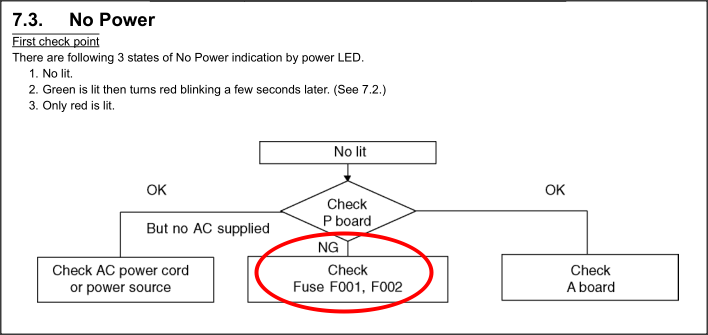
 .......
https://leoricksimon.blogspot.com/2014/05/panasonic-th-p42x30k-plasma-tv-power.html
Basic Interview Question Electrical interview questions:Different between megger and contact resistance meter? Answers:Megger used to measure cable resistance, conductor continuity, phase identification where as contact resistance meter used to measure low resistance like relays , contactors. Electrical interview questions :When we connect the capacitor bank in series ?Answers:we connect capacitor bank in series to improve the voltage profile at the load end in transmission line there is conside.......
https://ramganeshkce.blogspot.com/2011/11/electrical-interview-question2.html
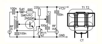 HF Bands QRP RF Linear Amplifier based power transistor 2N5590. This is a rather unusual QRP power RF amplifier design, with a wide frequency response; within three dB's from 300KHz to 30MHz. Overall gain is in the region of 16dB and the final output power may be well over four watts. The wide bandwidth is a result of the construction of the RF transformers, T1 a.......
https://radiofrequencyamplifier.blogspot.com/2011/09/4w-hf-bands-qrp-rf-linear-amplifier.html
I am still lingering around flyback transformer and never start my tesla coil design since i am too absorbed and keen to know how does the flyback transformer work. For your information, before i got to have the ferrite c cores from the original flyback transformer from CRT tv, i have purchased four ferrite rods from Ebay as i ve planned to made them into my own handmade ferrite core or frame. As the rods were still in my room and i ve got nothing to do with it therefore i decided to resume to t.......
https://yamanashimasamune.blogspot.com/2011/07/high-voltage-experiments-part-3.html
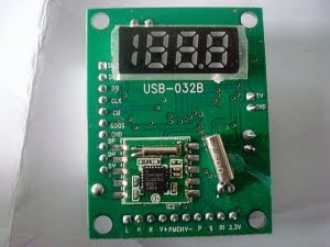 Published by www.ModemArea.com (Modem Unlocking Website). Aha, at last Now it is to make Usb Mp3 Player at home with Usb Mp3 Player Module. This Module can read MP3 files from a USB thumb drive and play it for you. I Found a compact sized USB Reader circuit, which has a Sleek IR remote control, Comes with small LED Based Display. (LED Based Seven Segment Display). I bought it from a local s.......
https://usbmpthree.blogspot.com/2011/02/how-to-make-mp3-player-at-home.html

In this article we learn how to make a multilevel (5 level) cascaded inverter circuit using a very simple concept developed by me. Let's learn more regarding the details. In this website so far I have developed, designed and introduced many sine wave inverter circuits using straightforward concepts and ordinary components such as IC 555, which happen to be more result oriented instead of being complex and full of theoretical jumbles. I have explained how simply a high power audio amplifier can b.......
http://www.homemade-circuits.com/2015/12/simple-5-level-cascaded-sine-wave.html
The single phasing preventer cum high low and unbalanced-supply voltage cutoff relay described here ensure complete safety for 3-phase machinery. Generally, induction motor burn out due to excessive voltage during off hour, very low voltage during peak hours, unequal phase voltage and single phasing (missing of one phase completely from 3-phase supply). It is therefore essential to install single phasing preventer in addition to the starter. Starter provide only overload protection and therefore.......
https://bestengineeringprojects.com/single-phasing-preventer-circuit
1 2 3