logic probe - Circuitos electrónicos

Logic probes are basic low cost easy to use digital testers - they can give a useful indication of the operation of many basic logic circuits . . . find out more.
Circuitos electrónicos
https://www.electronics-notes.com/articles/test-methods/logic-probes/what-is-a-logic-probe.php
An useful and easy to build Logic Probe with Pulse injector. An schematic of a
http://www.josepino.com/circuits/?logic_probe

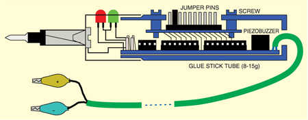
Using a conventional logic probe, it is difficult to determine what is happening at a point in a circuit above 50 Hz. The human eye isn't able to perceive the change which is happening at such a fast speed - for instance, the flickering of a tubelight. The audible logic probe described here helps to assess the […].......
http://electronicsforu.com/electronics-projects/audible-logic-probe
This circuit is a Logic Probe. It indicates the logic state of the node of any TTL logic circuit. To do that, we have to supply the probe with the same power of the circuit that we want to analyse: same Vcc and same GND. To check the logic level, we must connect the "Test" wire of the probe to the desired node of the circuit that we want to check........
http://www.circuit-finder.com/categories/tools-and-measuring/current-and-voltage/175/logic-probe
Build 3-State Logic Probe - For less than 10 bucks you can build a piece of test gear that you'll find is one of the handiest in your tool kit Back in the November 1998 edition of SILICON CHIP, we described a very handy 3-LED Logic Probe. The circuit is just as viable today as when it was published six years ago and literally thousands of kits have been sold. That's no surprise: a logic probe is one of the.......
http://archive.siliconchip.com.au/cms/A_102204/article.html
https://circuit-electronic.blogspot.com/2011/08/logic-probe-circuit.html
https://circuitschematic.blogspot.com/2010/12/audible-logic-probe-circuit-schematic.html
https://elecfreecircuit.blogspot.com/2013/04/logic-probe-with-sound-circuit.html
https://felicinwiring.blogspot.com/2013/04/logic-probe-with-pulse-indicator-circuit.html
https://itpbasicanalog.blogspot.com/2013/05/analyzing-frequencies-logic-probe.html
https://easycircuit012.blogspot.com.es/2013/08/01-simple-logic-probe-circuit.html
A handy and quick look-tool '5-State Digital IC and Circuit Tester' check by just touching this probe to different pins of various ICs and observing the logic levels.
https://bestengineeringprojects.com/electronics-projects/5-state-digital-ic-and-circuit-tester
 Per Retrophile's suggested tip involving my relay being wired incorrectly, I changed the wiring and figured out my mistake (thanks Retrophile) - I assumed incorrectly that the relay's pins fit logically to the pin layout in the schematic. . . they don't. Going to the documentation for this particular relay verifies that Retrophile's pin layout is cor.......
https://handsonelectronics.blogspot.com/2010/10/chapter-5-exercise-32-update-5.html
This simple logic probe has both LEDs on with no signal at the input but due to the nor gates connected to the probe, indicates correctly when a high or low signal is present. It also works correctly for pulse trains. Normally both LEDs are forward biased and therefore on, powered by the 12V supply. When a logic "high" is present at the probe, IC1a's output goes low sending IC1b's output high. This turns off LED1 but forward-biases (and turns on) LED2. Conversely, a logic "low" at the probe will.......
http://www.circuit-finder.com/categories/tools-and-measuring/current-and-voltage/924/simple-logic-probe
1 2 3