current indicator - Circuitos electrónicos

Motor Torque Control Circuit
Circuitos electrónicos
http://www.zen22142.zen.co.uk/Circuits/Interface/torque_control.htm
Site about circuits with full description, electronic design, circuit, schematic, diagram and PCB
Circuitos electrónicos
http://www.electronica-electronics.com/en
Circuitos electrónicos
https://circuitos-de-electronica.blogspot.com/2007/10/telephone-line-in-use-indicator-2.html
The circuit below uses some common components to turn on an LED whenever DC current above a certain level is detected. The circuit uses a very popular LM393 dual voltage comparator from National Semiconductor and a common 1N4148 signal diode. The diode acts as a crude 0.7v voltage reference. Only one of the comparators inside the 8 pin package is ..........
http://www.discovercircuits.com/H-Corner/DC-current indicaqtor4.htm
AC-Powered LEDUsually, LED is powered by DC supply, but this circuit can make the LED can be powered by AC supply. This circuit can be used as power indicator for Water pump. There are two circuit versions of AC-powered LED presented here. First is circuit for US or Canadian 110-120V 60Hz AC lines and European or Australian 220-230V 50Hz AC lines. Here is the circuit:  To limit.......
https://usbmpthree.blogspot.com/2011/02/ac-powered-led.html
Simple DIY Cable Continuity Tester  How to use This simple cable tester can be used to check 2 wire cable such as coax cable, telephone cable, audio cable and etc. Power the circuit using 9V battery. Plug in the cable and push "TEST" button. The dummy resistor is connected to the end of the cable which has 75ohm resistor inside. .......
https://leoricksimon.blogspot.com/2007/03/simple-cable-tester.html
Hi everyoneThis time I m gonna show you how a simple metal detector works. I will be using the oscillator circuit and the coil transformer in the previous post, which I have modified it into a simple metal detector. The circuit is shown below: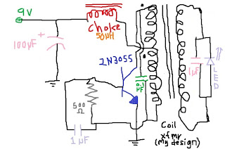 The LED is made an indicator for the detector. The coil transformer is the detection coil. Object is put into the centre of the coil for .......
https://yamanashimasamune.blogspot.com/2013/04/simple-metal-detector.html
The final part of the lap timer build along is also the easiest part, involving only the IR Detector and an optional LED with current limiting resistors. The previous steps can be found in the project index section of RC Arduino -https://rcarduino.blogspot.com/p/project-index. htmlA good introduction to IR Detectors is provided on the Ada Fruit website here -https://learn. adafruit.com/ir-sensorTo start our build we need a small section of strip board and a set of three wires for power, ground a.......
https://rcarduino.blogspot.com/2012/10/lap-timer-build-along-part-4-adding-ir.html

A universal current controlled automatic battery charger circuit with over discharge and over charge protection can be learned in th following post. The design also includes a 4 level charging status indicator using LEDs. The circuit was requested by Mr. Dendy. The Request To Mr. Swagatam Majumdar :I would like to ask and look forward to you to be made Automatic cellphone charger circuit 5 Volt and Automatic Lead Acid Battery Charger Circuit 12 V (in the schematic circuit and the first transform.......
http://www.homemade-circuits.com/2015/12/universal-battery-charger-circuit-with.html
 "I'm having some trouble figuring out why my turn signals don't flash. Is there a way to test the flasher unit before fiddling with other things? And just out of curiosity, how does the flasher unit work?"
 The flasher unit is the metal can shown in the pi.......
https://elektroniki.blogspot.com/2010/09/turn-signal-flasher-unit-et-104.html
Solar Power Center and Solar Charger CircuitTLC2272 - 10 Amp out Solar Power CenterThe SPC3 is a solar power center, it can handle all of the power functions for a solar charged 12 Volt DC system. The SPC3 contains a 9 amp photovoltaic charge controller, a 10 amp low voltage load disconnect circuit and a built-in white LED array for area illumination. The low voltage disconnect circuit has a load on-off switch, and a battery low voltage indicator. By using the SPC3 as the center of a solar power.......
https://basicelectronic.blogspot.com/2011/06/solar-power-center-and-solar-charger.html
Our purpose here is to explore the potential of PIC12F683 microcontroller for which we need a development board.The good thing is we are going to make our own board.The schematic and the actual board that I have built are shown below. I soldered all the components on a 12 x 8 cm general purpose prototyping board. Completed Board It has following features in it:1. A Regulated.......
https://picboard.blogspot.com/2010/02/make-your-own-pic12f683-development.html
Author: Huihui Duan, Chaonan Chen, Au Group ElectronicsAu SAE-J1939 Simulators are well designed devices capable of simulating majority of SAE-J1939 signals on a vehicle network. A typical SAE J1939-15 network topology is illustrated in Figure 1. 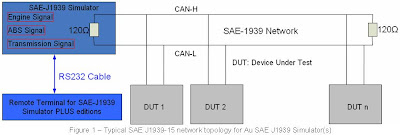 6 editions of SAE-J1939 simulator are provided by Au Group Electronics to meet various .......
https://augroups.blogspot.com/2009/02/user-manual-for-au-sae-j1939-simulator.html
The LTC®3895 is a high performance step-down switching regulator DC/DC controller that drives an all N-channel synchronous power MOSFET stage that can operate from input voltages up to 140V. A constant frequency current mode architecture allows a phase-lockable frequency of up to 850kHz. The gate drive voltage can be programmed from 5V to 10V to allow the use of logic or standard-level FETs to maximize efficiency. An integrated switch in the top gate driver eliminates the need for an external b.......
http://feedproxy.google.com/~r/LinearTechnologyFeed-Datasheets/~3/bbN6YAey4tY/LTC3895
This is a 1.2 - 12 V, max 1A power supply with a low voltage indicator LED. The indicator part incluedes three diodes and one LED. For example you are charging a battery, you can observe the charge status at that moment. Another advantage of this circuit, when the drawn current exceeds 1A (practically 0.85A), the current protector in LM317 intervens and LED indicator warns you about the very low output voltage. Be careful while choosing the transformer. Most of the products are specified as 1.......
http://www.electronics-diy.com/electronic_schematic.php?id=593
1 2 3