control relay - Circuitos electrónicos

Circuit diagrams and details of how to build an Alarm Control Keypad Operated Switch and a Multi-Zone Intruder Alarm System
Circuitos electrónicos
http://www.zen22142.zen.co.uk/ronj/k5s.html
Circuitos electrónicos
https://circuitos-de-electronica.blogspot.com/2007/10/sound-sensor.html
on off temperature control with relay circuit diagrams. Search DIY electronic projects and circuit diagrams with descriptions. Learn electronics.
http://www.high-voltage-lab.com/search/on-off-temperature-control-with-relay
 z124-127
 Solid State ReIays Figure 1. Hybrid SSR CONTROL SIGNAL OPTIONAL PREAMPLIFIER REED RELAY TRIAC TRIGGER CIRCUIT LOAD ISOLATING TRANSFORMER CONTROL DC-AC CONVERTER TRIAC TRIGGER CIRCUIT LOAD Figure 2. Transformer-Coupled SSR PHOTO-TRANSISTOR LED [. . ]
http://www.omega.com/pdf/temperature/Z/pdf/z124-127.pdf
This light activated relay circuit is simple form but can be useful various such as The alarm circuit, an more electronic control circuits such as ON-OFF
http://t.co/jcyFleyU4T
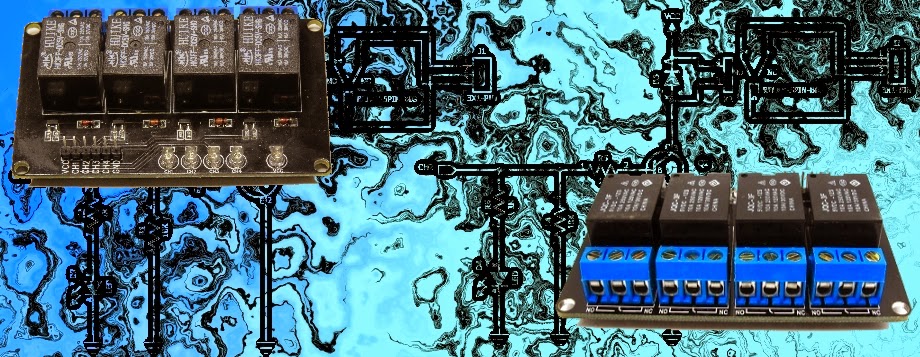 WARNING: Mishandling or incorrect or improper use of relays could result in
  serious personal injury or DEATH possible physical damage of the product faulty operation or create serious/dangerous hazards. Please make sure that you read and understand how .......
https://arduinobasics.blogspot.com/2014/09/relay-module.html
The leading free newsletter for PC-based data acquisition and control. This month: digital output control systems, automatically generating pre-formatted reports in Excel and relay switching.
https://www.windmill.co.uk/monitor71.html
 Almost all of the functionality of the "X10 Book" is included in this project and new features have been added.What's missing is the ability to drive relays and LED's. My thinking is to include such things as optional "add-ons". So a "relay pack" could be designed for lawn sprinklers. I'm cur.......
https://brohogan.blogspot.com/2009/10/nex10-functionality.html
I spent a bit of time rewiring the entire circuit for Experiment 32. . . taking one of my readers suggestions that the protoboard could have a bad insertion area, I moved all the wires to new locations. I then replaced the 555 chip with a new one and used my multimeter to confirm that the relay was getting higher voltage on the coil when a microswitch was pressed.Finally, as a last ditch effort after these efforts produced no change in results, I swapped out the 47uF capacitor with a 100uF. . . .......
https://handsonelectronics.blogspot.com/2011/01/jumping-to-experiment-34.html
Having had good experience with the Rapman's PIC32-based controller, I decided to stick with that MCU for my new printer. As I mentioned earlier, rather than buy a $1k+ C compiler from Microchip, I bought a much less expensive, full-featured BASIC compiler for the PIC32 {they also offer C and Pascal compilers} and a full development board from Mikroelektronika in Belgrade. Friday night, with the last of the z-axis brackets being printed on my Rapman and the 19 June exhibition in San Francisco co.......
https://technocraticanarchist.blogspot.com/2011/05/stepping-into-firmware.html
This project is a 3-channel IR remote control with 3 output relay and easy to build. Features: CPU PIC12F629 at 4MHz crystal for Tx/Rx, 3 channel output relay, The Tx use sleep mode for saving battery power, Use Phillips RC5 protocol, distance more than 7 m, Easy circuit to build and assembly and small amount of components. Uses RC5 protocol which is probably the most used by hobbyists, probably because the wide availability of cheap remote controls and easy to understand........
http://www.electronics-diy.com/electronic_schematic.php?id=495
Basic Interview Question Electrical interview questions:Different between megger and contact resistance meter? Answers:Megger used to measure cable resistance, conductor continuity, phase identification where as contact resistance meter used to measure low resistance like relays , contactors. Electrical interview questions :When we connect the capacitor bank in series ?Answers:we connect capacitor bank in series to improve the voltage profile at the load end in transmission line there is conside.......
https://ramganeshkce.blogspot.com/2011/11/electrical-interview-question2.html

The simple gate open and close controller circuit is designed to operate the gate through a couple of push buttons manually, it can be also modified for implementing the activation through a remote control. Referring to the shown, simple gate open, close controller circuit below, we can witness a rather straightforward configuration, essentially comprising of a transistor latch stage, a DPDT relay stage and a few push to ON/OFF switches. The push switches S3/S4 play an important role in the circ.......
https://www.homemade-circuits.com/2015/11/simple-gate-openclose-controller-circuit.html
Que necesitamos para Implementar un Control de Temperatura con Precisión regular ó Media. Es decir Donde el proceso nos permita jugar entre un rango de +-15º C. Vamos a necesitar un Control de Temperatura tipo ON - OFF. Un sensor de Temperatura ( Termocople ), Normalmente para estas aplicaciones Utilizamos un tipo "J" o tipo "K", según el rango de temperatura que queremos controlar. Otro de los elementos importantes en este sistema es Un Relevador de Potencia, que puede ser un Relevador mec�.......
https://dircasa-calora.blogspot.com/2009/11/como-implementar-un-sistema-de-control_19.html
This is a simple type remote control by using RF communication without microcontroller. In this project a remote has been designed for various home appliances like television, fan, lights, etc. It gives lot of comfort to the user since we can operate it by staying at one place. We can control any of the appliances by using this remote within the range of 400 foots. In this project consist of two sections, transmitter (remote) and receiver section. Whenever we are pressing any key in the remote i.......
https://electronicsfusion.blogspot.com/2011/10/remote-control-circuit-through-rf.html
1 2 3